Disassembly and Reassembly of the PlayStation 1 SCPH-9002 Console
Learn how to Disassembly and Reassembly the PS1 SCPH-9002 with this video:
Required Tools & Safety Precautions
Screwdriver: Phillips 1 or 2 screwdriver.
Safety Warning: Unplug the power cord entirely before starting. The Power Supply Unit (PSU) features internal capacitors that hold dangerous high-voltage charges even after the console is unplugged. Avoid touching exposed metal on the PSU board.
1. Disassembly Instruction Guide
1.1 Inversion
Flip the console upside down: Place the console face down on a soft, non-abrasive surface like an ESD mat or a clean microfiber towel to prevent scratching the top plastic shell.
1.2 Shell Screw Removal
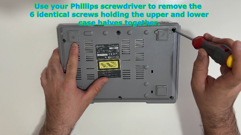
Remove outer casing screws: Use your Phillips screwdriver to extract the 6 identical outer screws located in the deep recesses on the bottom of the lower shell. Set these screws aside safely in a container.
1.3 Detaching Upper Casing
Detach the top cover: While holding both halves together, flip the console back to its normal right-side-up orientation. Gently lift the top cover straight up and off. If it catches, check that all 6 screws are completely loose and unthreaded.
1.4 Laser Disc Drive Extraction
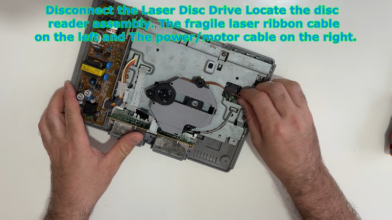
Locate the disc reader assembly: Identify the optical disc drive sitting in its recessed plastic tray.
Disconnect the laser ribbon cable: On the left side, locate the fragile flat orange/amber laser data ribbon. Grip the reinforced tab of the cable and pull it straight up out of its motherboard slot. Do not twist or pull the thin film directly.
Disconnect the power/motor cable: On the right side, locate the 4-pin bundled wire connector powering the spin/sled motors. Pinch the white plastic plug housing and lift it straight up to disconnect it from the motherboard.
Remove drive: Lift the optical drive module out of the console and place it in a safe, dust-free environment.
1.5 Controller Port Module Disconnection
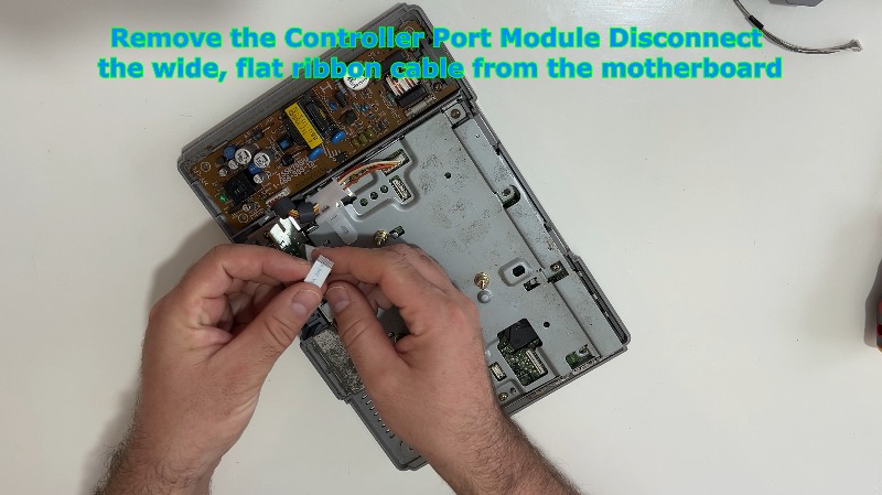
Disconnect the ribbon cable: Find the wide, flat silver ribbon cable connecting the front controller and memory card ports to the motherboard.
Unplug from board: Gently push or slide the ribbon cable connector upward out of its friction-fit socket on the motherboard. Leave the module sitting loosely in its slot for now.
1.6 Power Supply Unit (PSU) Wire Harness
Unplug the main power cable harness: Locate the white plastic wiring harness running from the power supply board to the main motherboard. Pinch the locking mechanism tab on the plastic plug and pull it straight up to free the motherboard from the internal power lines.
1.7 Motherboard and Top EMI Shield Removal
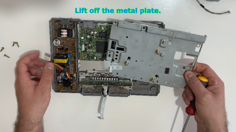
Remove top metal shield screws: Locate the large sheet-metal Electromagnetic Interference (EMI) shield covering the motherboard. Use your Phillips screwdriver to remove the 4 remaining screws securing this metal tin top cover to the main board.
Lift off the metal plate: Lift the top EMI metal shield straight up and off the motherboard.
1.8 Motherboard Deep Extraction
Remove internal securing screws: Remove the 2 remaining screws that anchor the bare green motherboard directly down into the lower chassis pillars.
Extract the mainboard: Lift the green motherboard straight up and out. This separates it from the final bottom metal shielding plate underneath it. Handle it exclusively by the edges to prevent static damage to the microchips.
1.9 Controller Port Module Complete Removal
Remove the controller port module: Now that the motherboard and surrounding constraints are removed, lift the plastic controller and memory card port block straight out of its dedicated front retention tracks in the lower plastic shell.
1.10 Power Supply Unit (PSU) Board Extraction
Remove PSU screws: Locate the two Phillips screws anchoring the yellow/brown internal power supply board to the bottom plastic shell. Unthread them fully.
Extract power board: Carefully lift the power board straight up and out by holding it by its plastic insulation sheet or its edges. Avoid touching the solder tracks or large cylindrical capacitors to prevent static or electrical shock.
1.11 Bottom Shield Removal
Shield on the bottom: Lift out the remaining large bottom metal shielding plate resting at the very bottom of the lower plastic shell. The lower plastic shell should now be completely empty.
1.12 Inspection
Let's take a closer look at the motherboard: With the board fully extracted, you can now inspect the surface components. Check the capacitors for leakage, clear any dust buildup with compressed air, or access the underside trace lines for diagnostic testing or modding.
2. Reassembly Instruction Guide
2.1 Base Plate Installation
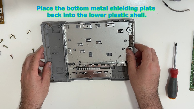
Place the bottom metal shielding plate back: Orient the large bottom metal shield correctly and drop it flat into the lower plastic shell. Align its cutout paths over the internal plastic screw pillars.
2.2 Controller Port Mounting
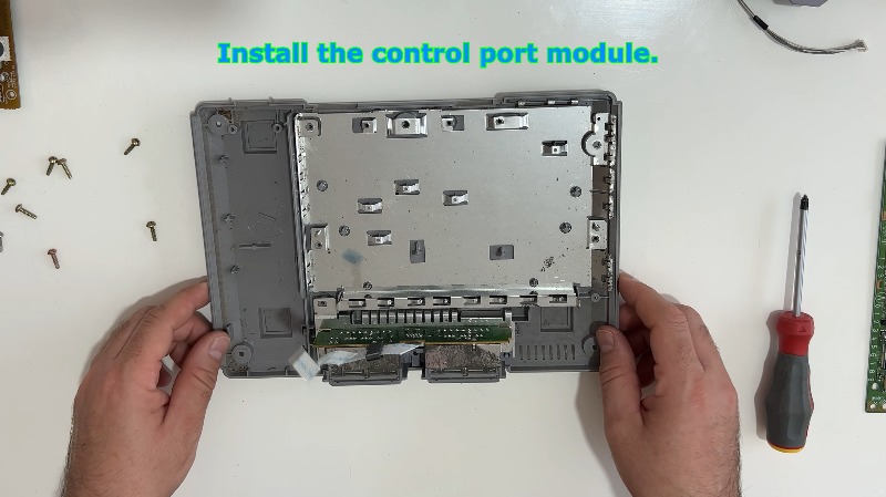
Install the control port module: Slide the controller port block back into its vertical side tracks at the front of the plastic shell. Ensure the wide ribbon cable points inward toward the center of the console.
2.3 Power Supply Unit Installation
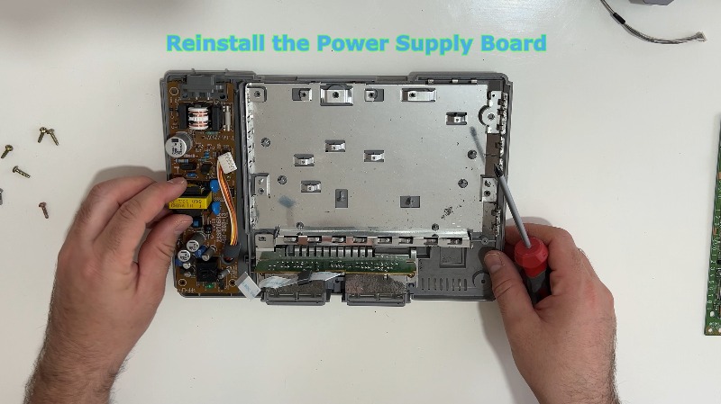
Reinstall the power supply board: Lower the PSU board straight down onto its plastic alignment pins on the left side of the bottom shell. Ensure the clear plastic insulation sheet is tucked properly underneath it.
Secure the board: Drive the 2 designated PSU screws back into the power board to lock it firmly into the lower shell pillars.
2.4 Motherboard Alignment and Anchorage
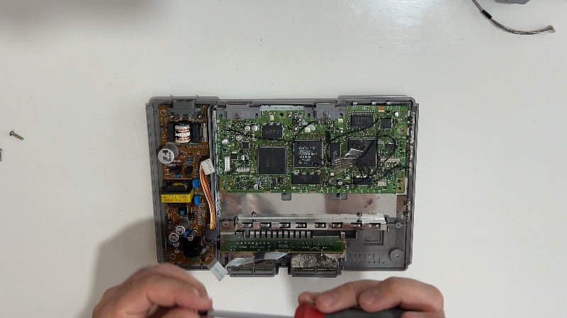
Align the motherboard: Lower the green motherboard into the center chassis directly over the bottom shield. Ensure the rear video (AV Multi Out) and serial ports fit perfectly into their molded cutouts at the back of the plastic case.
Secure the mainboard: Reinstall the 2 designated internal screws into the bare motherboard holes to anchor it down into the chassis frame.
2.5 Top EMI Shield Mounting
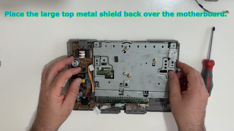
Place the large top metal shield back: Overlay the large top metal EMI shield directly over the motherboard, matching up all corresponding screw hole openings.
Tighten the shield screws: Drive and tighten the 4 motherboard screws down through the shield tabs to secure the metal shield and motherboard tightly together to the chassis underneath.
2.6 Intercomponent Connection
Reconnect the controller module ribbon: Grab the wide controller port ribbon cable. Push its stiffened end straight down into the provided friction connector on the front edge of the motherboard until it is firmly seated.
Plugin the plastic power harness: Take the bundled power wire harness coming from the PSU and plug it back into the matching white motherboard socket. Press down firmly until it clicks or seats fully.
2.7 Disc Drive Reinstallation
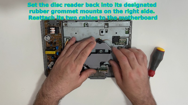
Set the disc reader back: Lower the optical disc drive module back into its four rubber vibration-dampening grommet mounts inside the chassis.
Plug in the data ribbon: Carefully align the orange laser ribbon cable and push it down vertically into its motherboard slot. Ensure it sits straight and fully plugged in.
Plug in the motor cable: Push the 4-pin bundled wire connector back into the corresponding white power socket on the right side of the motherboard.
2.8 Final Shell Closure
Attach the top shell: Place the top plastic console cover straight down over the fully assembled lower chassis. Ensure it sits perfectly flush with the bottom shell all the way around with no gaps.
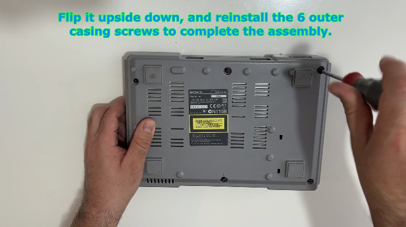
Invert the console: Securely hold the top and bottom case halves together, then carefully flip the entire console upside down.
Secure outer screws: Drop the 6 identical outer screws back into their bottom chassis holes. Tighten them down snugly with your Phillips screwdriver in a cross-pattern to distribute the pressure evenly. Do not overtighten, as you could crack the vintage plastic threads. Flip the console right-side up to complete the build.
---