
This is a comprehensive, step-by-step guide for disassembling the PlayStation 4 Slim console CUH-2016B.
How to open the PS4 Slim, clean the dust, replace the thermal paste, Laser Clean and replacing the CMOS Battery with this video:
PlayStation 4 Slim Deep Maintenance Guide. This comprehensive, highly detailed guide will walk you through the process of disassembling, cleaning, and replacing the thermal paste, Laser Clean and of course replacing the CMOS Battery on the PlayStation 4 Slim CUH-2016B.
You will need a Phillips #1 screwdriver, a Torx T8 Security screwdriver (with a center hole), 90%+ Isopropyl Alcohol (IPA), cotton swabs, and high-quality thermal paste (like Arctic MX-4). Note: While the small components surrounding the processors use solid thermal pads, the core CPU (Cell) and GPU (RSX) processors require liquid thermal paste, which must be fully cleaned and replaced once opened.
------------------------------
Phase 1: Hard Drive & Outer Covers Removal
- Locate the plastic corner cover on the rear left angle of the console's shell. Slide it to the right to unclip and remove it, exposing the hard drive bracket.
- Use a Phillips screwdriver to remove the single large, customized screw marked with the PlayStation symbols (×∘□△) that holds the drive in place.
- Rotate the console to the hard drive slot on the side panel.
- Pull the black ribbon tab straight out firmly to slide the Hard Drive caddy completely out of the console body. Set it aside safely.
- Return to the side of the rear casing where the safety and warranty elements reside.
- Peel off the plastic warranty sticker near the back ports carefully to reveal a hidden security screw underneath.
- Use a T8 Security Torx screwdriver to remove this hidden safety screw.
- Turn the console back over so it is sitting bottom side up on your workspace.
- Pry up on the two front corners of the bottom plastic cover, releasing the internal clips, and slide it away to remove it entirely.
- Critical Attention Note: Keep an eye out for the flat cable plugged in at an angle! Ensure it is not tugged or stressed.
- Preparation Note: On this exposed side, locate and loosen the Phillips screw securing the power supply unit before flipping the unit again.
- Turn the PS4 slim console over so the top side faces up.
- Pry up on the two front corners of the top plastic cover with a steady upward pull, then slide it away to remove it and expose the upper internal metal plate.
Phase 2: Power Supply Unit (PSU) & Shielding Disassembly
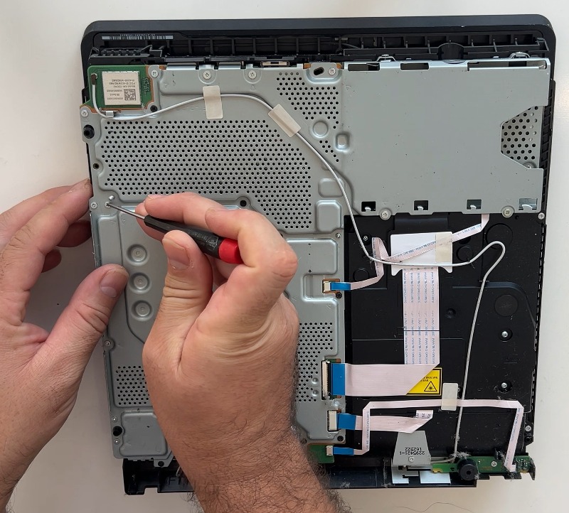
- Remove four Phillips screws that secure the outer perimeter framework of the power supply unit.
- Remove the three Torx T8 screws that firmly anchor the structural shielding segments around the area.
- Remove the metal shield covering the localized power circuitry section.
- Unscrew the screw from the Wi-Fi antenna mount and carefully detach it from the side channel routing path where it sits embedded.
- Pull the power supply unit straight up out of its deep cavity, flipping it over smoothly to place it upside down next to the opening.
- Pull the white 4-pin power connector directly from its socket on the motherboard. Do not pull on the wires themselves; pull the plastic plug housing with your fingers or tweezers to avoid tearing the cables. Lift the PSU completely out of the chassis.
- Turn the console to the other side to work directly on the motherboard surface.
- Disconnect all ribbon cables from their respective surface mounts on the motherboard by popping open their tiny plastic locking collars first.
- Unplug the small fan power loop connector by gripping its plug firmly and sliding it clear of the terminal.
- Disconnect the small wireless antenna cable connector by gently lifting the round golden plug vertically off its tiny board terminal.
- Unscrew the roughly 29 matching silver and black screws that fasten down the expansive main metal shielding plate. Keep these meticulously sorted.
- Remove the metal plate to fully expose the green motherboard underneath, and carefully remove the wireless antenna cable from the metal plate channels. Component Note: Meticulously note the thermal pads attached to the plate; make sure they are returned to the metal shield in their original positions.
- Turn the PS4 slim console over.
- Disconnect the small wireless antenna cable connectors located on this alternate layout profile.
Phase 3: Core Board Removal & De-Crusting
- Turn the PS4 slim console over once more to access the primary retention components.
- Loosen the main processor clamp: Special attention should be paid to the two large screws of the cooler clamp that determine the direct mechanical pressure on the main processor chip (APU). Unroll them gradually, alternating making one full circle on each screw to balance the relaxation of spring tension.
- Pull the white 4-pin power connector cleanly from the motherboard interface (once again, pulling exclusively on the plastic plug rather than the raw wire strands).
- Carefully lift the motherboard out of the plastic frame housing by its edges, avoiding snagging any loose internal components. Component Note: Pay close, active attention to the small thermal pads on the board chips; be careful not to lose them or let them fall into the casing.
- Clean the old, dry thermal paste thoroughly from both the reflective surface of the processor (APU) and the matching flat radiator block on the frame. Wipe both surfaces down with cotton swabs or wipes saturated with high-percentage alcohol until the metal surfaces are perfectly shiny and mirrored.
Phase 4: Cooling Fan & Optical Drive Overhaul
- Turn the PS4 slim console over.
- Unscrew the two screws that hold the main fan housing down on this side of the structural interior.
- Turn the PS4 slim console over.
- Unscrew the remaining screws still anchoring the primary structural layout from the metal plate.
- Remove the metal plate on which the heatsink is located to separate the core cooling mechanics.
- Unscrew the remaining two screws holding the fan assembly from the reverse side orientation.
- Remove the fan completely out of its molded seating tray.
- Remove dust completely from the fan blades and the dense heatsink fins; you can also do it with a vacuum cleaner or a compressor to blow/suck away all compacted debris.
- Remove all screws on the disc reader unit to isolate the optical assembly.
- Remove the power button panel module carefully from its position along the rim.
- Remove the wireless antenna component assembly from its anchor position.
- Remove the disc drive completely out of the interior skeletal frame.
- Remove the two screws from the disk drive cover plate to open the internal optical chamber.
- Clean the lens of the laser very gently using a clean ear swab lightly soaked in isopropyl alcohol. Avoid rubbing with excessive force.
Phase 5: Component Restoration & Internal Reassembly
- Put the Metal Cover back on the disk drive and securely tighten the two screws you just removed from it.
- Return the disk drive to the case frame structure, aligning it with the mounting points, and tighten the screws down completely.
- Install the power button panel back into its designated frame slot and tighten the screw.
- Mount the wireless antenna component back into position and tighten the screw.
- Put the clean fan back in place inside its housing track and tighten the two screws to immobilize it.
- Reinstall the metal plate with the heatsink into the housing frame, matching up all internal alignment pins.
- Tighten the screws that secure the metal plate to the housing structure securely.
- Apply New Paste: Place a clean, uniform application of new thermal paste right in the center of the clean processor chip (APU).
- Check Thermal Pads: Conduct a visual audit to ensure the small black rubbery thermal pads sitting on the components are still in place and didn't fall off during handling. Maintenance Option: Take this opportunity to replace the CR2032 coin battery on the motherboard if you wish, while the board is exposed.
- Reseat the Motherboard: Lay the motherboard carefully back down into its precise position over the heatsink alignment points.
- Connect the power cable back to its corresponding receiver terminal on the motherboard surface.
- Secure the APU: Place the X-shaped APU clamp back over the center chip and tighten the two Phillips screws evenly, gradually tightening them, alternating one full turn on each screw to balance the mechanical pressure across the processor silicon.
- Check Thermal Pads: Perform a final check to ensure the small black rubbery thermal pads sitting on the board chips are still in place and didn't fall off during board manipulation.
- Set the large metal chassis shield back down squarely over the top surface of the motherboard layout.
- Screw in the Board: Re-insert and securely tighten the 29 matching silver and black screws back into their respective threaded holes across the plate.
- Route the Wi-Fi antenna cable to the top of the metal shield along its original channel and firmly connect its connector to the designated terminal plug.
- Connect all the flat ribbon cables and the fan cable back into their motherboard ports, firmly locking down any retention tabs.
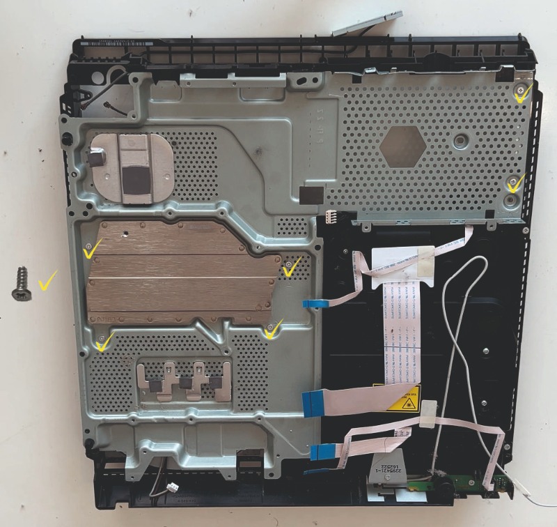
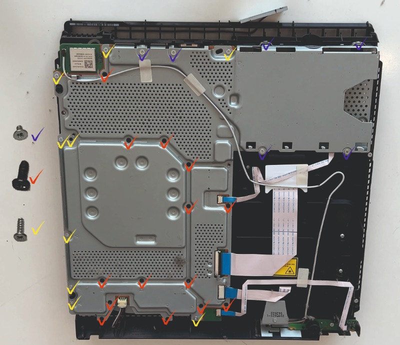
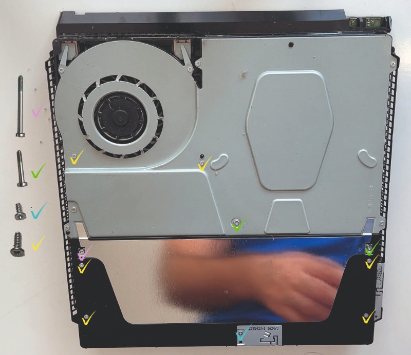
PS4 Slim Screw Layout Breakdown
Phase 6: Power Supply Unit & Outer Casing Re-Closure
- Turn the PS4 slim console over to prepare for power block installation.
- Plug the white 4-pin motherboard power cable back into the PSU receptacle securely.
- Run the two Wi-Fi antenna cables through the metal shield framework channels and connect their connectors to their matching board nodes.
- Carefully press the power supply unit back into its seat within the chassis cavity. Simultaneously, put the Wi-Fi antenna back in its seat and screw it in with a screw to fix it firmly.
- Place the metal shield on the power supply assembly unit.
- Tighten all the remaining structural screws on this side of the PS4 Slim console chassis.
- Turn the PS4 slim console over once more.
- Tighten the rear Phillips screw that secures the power supply unit from the opposite side entry point.
- Replace the bottom cover in a sliding motion from the back edge to the front, keeping it level, and press down firmly until the front plastic clips click into place.
- Turn the PS4 slim console over.
- Replace the top cover in the same way, sliding it horizontally forward from the rear and snapping the front retaining anchors shut.
- Slide the Hard Drive back into its tray opening along the side channel until it seats completely against the internal SATA connector port.
- Tighten its customized PlayStation screw back into the bracket framework to secure the drive.
- Snap the outer plastic HDD corner cover back in place by sliding it firmly to the left.
- Re-insert the Torx T8 security screw on the back casing panel exactly where the original warranty sticker sat, sealing the console frame shut.