
Opening replacing thermal paste and upgrade wireless card, CMOS battery, SSD.
This video will show you how to Opening replacing thermal paste and upgrade wireless card, CMOS battery, SSD on Acer Spin 3:
Acer Spin 3 SP313-51N with intel i7-1165G7 11th or SP313 SP314 SP315
- Screwdriver: Phillips #0 or #00 precision screwdriver.
- Prying Tools: Plastic spudger, guitar pick, or opening tool (safer than fingernails).
- Cleaning: 90%+ Isopropyl alcohol (rubbing alcohol) and microfiber or lint-free wipes.
- Thermal Paste: High-quality compound (e.g., Arctic MX-4 MX-6 or Noctua NT-H1).
- Workspace: Clean, flat, non-magnetic, and static-free surface.
Step 1: External Preparation
1. Power Down: Shut down Windows completely (do not use sleep or hibernate). Unplug the AC power adapter.
2. Remove the Stylus: Pull the active touchscreen pen out of its dedicated storage garage on the side of the chassis.
3. Position the Laptop: Close the lid, flip the laptop upside down, and place it on a soft surface to avoid scratching the top cover.
Step 2: Chassis Opening
1. Remove Base Screws: Use your Phillips screwdriver to remove all visible screws from the bottom cover. Keep them organized, as some Acer models use different screw lengths for the front and back rows.
2. Pop the Clips: Insert a plastic prying tool into the seam where the bottom cover meets the keyboard deck. Gently slide it around the perimeter to release the plastic tabs.
3. Lift the Cover: Carefully lift the bottom panel straight up and set it aside.
Step 3: Safety First (Disconnect Battery)
1. Unplug the Battery: Locate the main battery connector attached to the motherboard.
2. The Pull Method: Grip the plastic connector firmly and pull it straight back out of its socket (parallel to the motherboard). Do not pry upward, or you may rip the socket off the board.
3. Drain Residual Charge: Press and hold the laptop's physical power button for 10–15 seconds to safely drain any electricity left in the capacitors.
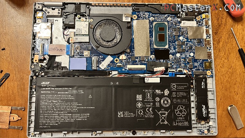
Step 4: Wi-Fi Card Upgrade (AX201 to BE200 Wi-Fi 7)
- Disconnect Antennas: Use tweezers or a fingernail to gently pry the gold coaxial antenna terminals vertically straight up off the old AX201 card.
- Unscrew: Remove the single Phillips screw holding the wireless card down. The card will naturally pop up at a slight angle.
- Swap Cards: Pull the old card out of the M.2 slot. Insert your new Intel BE200 (Wi-Fi 7) card into the slot at the same angle, press down, and secure it with the screw.
- Reconnect Antennas: Align the small antenna caps directly over the gold posts of the new card. Press straight down firmly until you feel a distinct click. (Note: Make sure your specific Acer Spin 3 processor supports the BE200, as it requires a standard PCIe/USB-based M.2 slot, unlike the CNVio-only AX201).
- I tested the intel BE200NGW Wi-Fi 7 card on an Acer Spin 3 SP313-51N with intel i7-1165G7 11th and it works great.
- Tip: Remember to download and install the official Intel BE200 Bluetooth and Wi-Fi drivers once you boot into Windows to enable Wi-Fi 7 functionality!
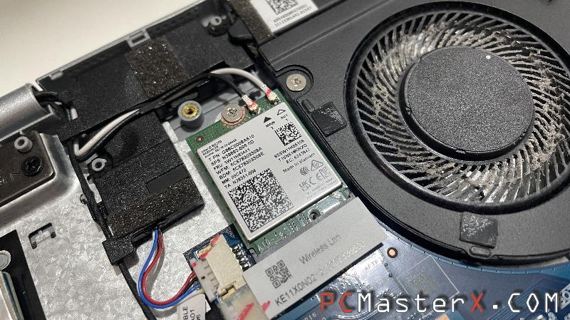
Step 5: Thermal Paste Replacement
1. Loosen Heatsink Screws: Locate the copper heatsink assembly covering the CPU. Loosen the retention screws in a crosswise/diagonal pattern (follow the numbers stamped on the metal, usually 1 through 4) to prevent uneven pressure on the delicate silicon die.
2. Remove Heatsink: Lift the cooler assembly straight up and out of the laptop.
3. Clean the Surfaces: Moisten a lint-free cloth with isopropyl alcohol. Thoroughly wipe away the old, crusty grey thermal paste from both the copper underside of the heatsink and the reflective CPU die until they look completely shiny and brand new.
4. Apply New Paste: Dispense a small, pea-sized drop (or a small line) of fresh thermal compound directly onto the center of the clean CPU die. Do not over-apply.
5. Reinstall Heatsink: Lower the heatsink vertically back onto the chip. Tighten the screws using the same crosswise pattern (1-2-3-4) to guarantee an even spread of the paste.
Step 6: M.2 SSD Reference (Optional Maintenance)
- Primary M.2 SSD: Secured by a single Phillips screw. It features a thermal pad underneath the drive to dissipate heat to the motherboard/chassis.
- Secondary M.2 SSD Slot: Also secured by a single Phillips screw. The motherboard's circular CR2032 BIOS/CMOS coin-cell battery sits directly underneath this storage area.
Step 7: Reassembly
- Reconnect Battery: Align the battery wire terminal pin block and slide it firmly back into its motherboard socket.
- Snap Casing: Align the bottom plastic cover over the laptop frame. Press firmly down along all the edges until you hear the plastic tabs click shut.
- Secure Screws: Thread all the external base screws back into their original slots and tighten them.
- Finish Up: Slide the touchscreen pen back into its slot, flip the laptop over, plug in the power brick, and boot it up.